Playing with air pressure rockets is really awesome, I used to take on of these Masafi bottles, but water hose in (tight fit), pump water -> after sometime, the air pressure inside will be high enough that you can't hold it anymore, then point up and release and BOOOOM
That what happen with one bottle, so what about a whole rocket??
so, I set to make a rocket, which currently is a big fail because I did not have a proper air sealing material,,,
concept of one bottle, first pressurize then release (click to enlarg)
When I connected two, the leak happened as shown
The concept of the Multi-Masafi Water-Air Rocket (cross section showing 2 of the six C-Engine Cylinder :P) and yea, C for Circular, and "strobe" should be "straw"
The pictures above does not show the actual bottle size, below it does (okay, to some extent, excuse my hand skills on MS Paint)
It also shows the expected aerodynamic behavior (the rocket is going up)
well, if it failed/drifted etc am gonna add a cone/rocket case to remove the effect of the straws / bottle shape
I collected bottles
drilled the holes
assembled with duct tape and glue gun:
The problem is that glue gun does not withstand air pressure and fails, I'll continue this when I have what I need, till that time, this rocket which looks like one of Yuri's buildings (Red Alert) will stay on the wall
Recently, we moved to another home, unfortunately (or fortunately) the garage door does not work, we open it manually currently, we requested the house owner to fix it but they said that they tried many times but failed, so what does this mean for an EE lover?
An awesomeness of course, a new toy to play with, a new game to reverse engineering :)
I tried the manual button, the motor does work but the door does not move, I tried assisting it by giving it a push but no hope, so apparently, the gears are broken/loose etc a mechanical problem in short.
not only that, but also, we do not have the remote controller, so apparently I'll have to hack it to put my own wireless connection, later..
now lets start playing:
The box:
Now I need to remove the bottom to reach the mechanical problem and fix it, I had to use a lot of force to open these two blots on bottom:
notice how the spanner got bended in the image below
What about this dried-sanded grease:
overview of the inside,
top right is the motor with three wires (I don't have experience with motors, so your help is apperciated here, the motor has three wires two of them are connected the big cylinder you can see on the top left [I guess a cap??!] and there is a third wire)
What is this motor? which type? what are the three wires?
Is it a capacitor really? why it is there?
top left a capacitor (I guess)
below it is the transformer
and on bottom the PCB
Wireless chip on right side of PCB
Connection Header on top of PCB
The circuit
started labeling some wires
I then used WD-40 and sprayed on the screws to remove the PCB (Along with the transformer which is soldered to the PCB)
Now I need to remove wires, so I took note of all connections and labeled wires
Before that, I decided to test it, found that the motor is actually rotating as well as the output shaft
so, I reconnected it up again, but again it does not work!!!
conclusion: the mechanical assembly is having a problem which I cannot fix
So, I decided that its enough for my young brother and sister wasting their money in the stupid malls games and will make my home game arena!
Luckily I had an old computer table which was about to be thrown, the 15mm wood will help a lot to make strong bases. (Kids games needs to be 10x military ratings)
Starting with a simple one, Sparkfun Simon game in a big scale, basically I'll buy their kit replacing the switches with big domes
I started today with the base, can't continue as I have only one dome push button
First, I took dimensions of available wood real-estate and choose the appropriate part, its a 30*48 cm surface with about half meter height
face is shown below, dimensions in mm
then I proceeded to cutting with jigsaw and drilling, added duct tape on the edges and the result:
To be continued ... after getting Simon kit and Dome Push buttons
Finally, got them, oh and Sparkfun did an awesome job by replacing bulb with LED so I don't need to waste time modifying it :)
Then I decided to display current level, I modified the code as following:
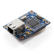
Using this guy was awesome, only need to connect two 3.3v pins, four GND pins, Rx0, Tx0. Then from PC use configuration tool to connect/configure and download firmare/webpages.
Below, I was testing in external ATmega168 before using the server (which has ATmega128 with pins you can use for I/O ADC etc)
Ethernet link - blinking!
webpage:
I've connected my relay driver to PB4 pin (on J2) which is LED0 on the WIZ200web development board, so I was able to control the light.
After that I decided to make two interfaces, one from PC "PC Station" and an "Android Station" and maybe also "iPhone Station"
I started with the simplest, "PC Station" for which I used Visual Basic:
The PC Station is working fine, however, there is small problems with changing the IP Address, if the connection is successful and I tried to change the ip address, it would still say "connected"
Also, I've not implemented Syncing data yet
Since It is working, I thought I'd move to the next step, Android!
The UI on Virtual Manager
I am able so far to toggle the picture ON/OFF, however, I am still looking for how to control the light :D