What happens when two awesomesness meet together?
Well, we get 2x AWESOMENESS :)
So, I've got the BeagleBone to talk to my AVR ATmega328, and here is how, from the scratch up to running.
Here is a list of what I used:
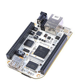

BeagleBone board - (http://beagleboard.org/Products/BeagleBone)
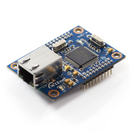
STK500 Board - (http://www.atmel.com/tools/STK500.aspx)
Sparkfun's Logic Level converter - (https://www.sparkfun.com/products/8745)
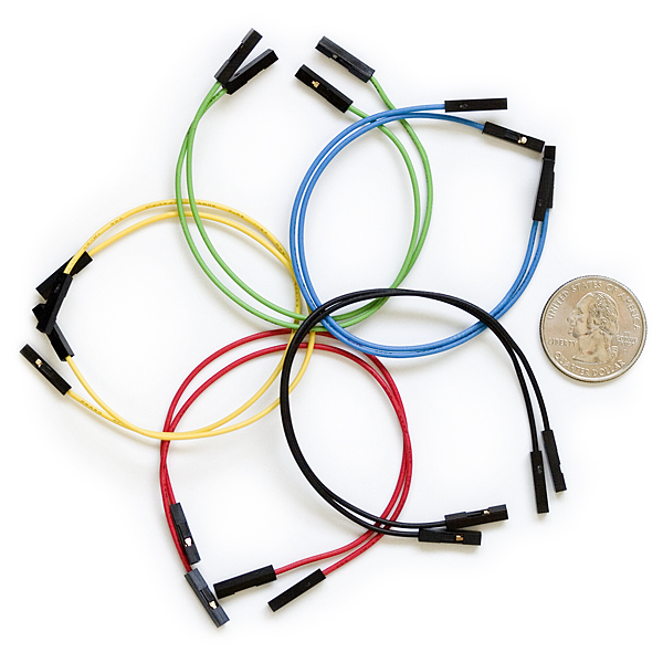
A mix of jumper wires
-----------------------------
Although I have used the ATMEL's STK500 board, you can use any other programmer
-----------------------------
I am not an expert or any thing close to it, I am writing what I did and learned for the convenience of other people
Step 1: Installing Ubuntu 13.04 "Raring" on the BeagleBone
source 1: elinux Wiki (http://elinux.org/BeagleBoardUbuntu)
source 2: GigaMegaBlog (http://www.gigamegablog.com/2012/09/03/ubuntu-on-the-beaglebone-enabling-analog-in-pwm-i2c-and-spi/)
the last step would be:
note the red X, this should be replaced with the correct letter according to what ID your PC assigns to the SD card
e,g,:
After finishing, the SD card should be ready, take it out from the PC and plug it in the beaglebone.
Connect your beaglebone to your router using an Ethernet cable, this is needed for downloading software and for easy access
Connect your beaglebone to a power source (for now, use the mini-USB port and connect it to your PC)
wait until Ubuntu loads up, it takes about a couple of minutes
using Putty, we can access the beaglebone to issue commands, this needs an SSH-server enabled on the beagle.

if it connect, that is awesome, and you can skip the following section.
if it fails, we'll need to connect through serial connection:
On a windows PC, Check your device manager
On a Ubuntu machine, check the contents of the devices directory
check before and after connecting your beaglebone, you will find that an extra serial port is available, open that port in a serial terminal at 115200 baud rate, and hit the tiny reset button on the beaglebone (next to the 4 user LEDs),
You will see the system booting up, wait until it is ready and then do the following:
source: https://help.ubuntu.com/12.04/serverguide/openssh-server.html
The SSH server should be up and running now and you should be able to remote connect using putty with the settings mentioned above.
The default username and password are
ubuntu
temppwd
That is, if you have not changed the password, if so please do so as soon as possible since your beagle is now on the internet with an SSH door
Step 2: The I2C interface
source: http://www.gigamegablog.com/2012/11/04/beaglebone-coding-101-i2c/
You have one usable I2C interface, that is i2c-3, on BeagleBone System Reference Manual PG. 59, it is refered to as I2C2_SCL and I2C2_SDA (Port 9:19, 9:20)
First, let us check the I2C interface:

Let us connect some wires now, but first we should shutdown Ubuntu and unplug the USB cable
wait for 5~10 seconds till the system shutdown, then unplug the USB cable
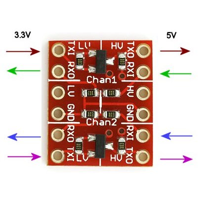
connect the circuit as shown below (modified picture from sparkfun (https://www.sparkfun.com/products/8745)):
Also, while you are connecting, connect an LED to PB0 and another to PB1 on the ATmega

Download and unzip the example code from:
https://github.com/MuazSalah/BeagleBone_ATmega
https://github.com/MuazSalah/BeagleBone_ATmega/archive/master.zip
Remember to change the makefile according to your hardware
Compile and program your ATmega, it will be assigned as an I2C slave at address 0x0A
Power up your BeagleBone again, after about 20 seconds, you will be able to SSH to it, when so, issue the command

download and unzip the example code:
run the python code:


Additional resources:
Enabling file sharing (NAS) on the BeagleBone
http://elinux.org/R-Pi_NAS
This a link for a tutorial on Raspberry PI, however, it is exactly similar to BeagleBone except that the service (or deamon) name is smbd and not samba, so you say
Well, we get 2x AWESOMENESS :)
So, I've got the BeagleBone to talk to my AVR ATmega328, and here is how, from the scratch up to running.
Here is a list of what I used:
BeagleBone board - (http://beagleboard.org/Products/BeagleBone)
STK500 Board - (http://www.atmel.com/tools/STK500.aspx)
Sparkfun's Logic Level converter - (https://www.sparkfun.com/products/8745)
A mix of jumper wires
-----------------------------
Although I have used the ATMEL's STK500 board, you can use any other programmer
-----------------------------
I am not an expert or any thing close to it, I am writing what I did and learned for the convenience of other people
Step 1: Installing Ubuntu 13.04 "Raring" on the BeagleBone
source 1: elinux Wiki (http://elinux.org/BeagleBoardUbuntu)
source 2: GigaMegaBlog (http://www.gigamegablog.com/2012/09/03/ubuntu-on-the-beaglebone-enabling-analog-in-pwm-i2c-and-spi/)
1.1 - On a linux machine, follow the following tutorial http://elinux.org/BeagleBoardUbuntu#Raring_13.04_armhf
the last step would be:
sudo ./setup_sdcard.sh --mmc /dev/sdX --uboot bone
note the red X, this should be replaced with the correct letter according to what ID your PC assigns to the SD card
e,g,:
sudo ./setup_sdcard.sh --mmc /dev/sdg --uboot bone
After finishing, the SD card should be ready, take it out from the PC and plug it in the beaglebone.
Connect your beaglebone to your router using an Ethernet cable, this is needed for downloading software and for easy access
Connect your beaglebone to a power source (for now, use the mini-USB port and connect it to your PC)
wait until Ubuntu loads up, it takes about a couple of minutes
using Putty, we can access the beaglebone to issue commands, this needs an SSH-server enabled on the beagle.

try to connect by choosing the options as above:
Connection type: SSH
Host Name: arm
if it connect, that is awesome, and you can skip the following section.
if it fails, we'll need to connect through serial connection:
On a windows PC, Check your device manager
On a Ubuntu machine, check the contents of the devices directory
ls /dev
check before and after connecting your beaglebone, you will find that an extra serial port is available, open that port in a serial terminal at 115200 baud rate, and hit the tiny reset button on the beaglebone (next to the 4 user LEDs),
You will see the system booting up, wait until it is ready and then do the following:
source: https://help.ubuntu.com/12.04/serverguide/openssh-server.html
sudo apt-get install openssh-server
sudo /etc/init.d/ssh restart
The SSH server should be up and running now and you should be able to remote connect using putty with the settings mentioned above.
The default username and password are
ubuntu
temppwd
That is, if you have not changed the password, if so please do so as soon as possible since your beagle is now on the internet with an SSH door
sudo passwd
Step 2: The I2C interface
source: http://www.gigamegablog.com/2012/11/04/beaglebone-coding-101-i2c/
You have one usable I2C interface, that is i2c-3, on BeagleBone System Reference Manual PG. 59, it is refered to as I2C2_SCL and I2C2_SDA (Port 9:19, 9:20)
First, let us check the I2C interface:
sudo i2cdetect -r -y 3
The output should be something like:
Let us connect some wires now, but first we should shutdown Ubuntu and unplug the USB cable
sudo shutdown -h now
wait for 5~10 seconds till the system shutdown, then unplug the USB cable
connect the circuit as shown below (modified picture from sparkfun (https://www.sparkfun.com/products/8745)):
Also, while you are connecting, connect an LED to PB0 and another to PB1 on the ATmega

Download and unzip the example code from:
https://github.com/MuazSalah/BeagleBone_ATmega
https://github.com/MuazSalah/BeagleBone_ATmega/archive/master.zip
Remember to change the makefile according to your hardware
Power up your BeagleBone again, after about 20 seconds, you will be able to SSH to it, when so, issue the command
sudo i2cdetect -r -y 3
download and unzip the example code:
wget https://github.com/MuazSalah/BeagleBone_ATmega/archive/master.zip
sudo apt-get install unzip
unzip master.zip
cd BeagleBone_ATmega-master/BeagleBone
run the python code:
sudo python LEDs_Blink.py


Additional resources:
Enabling file sharing (NAS) on the BeagleBone
http://elinux.org/R-Pi_NAS
This a link for a tutorial on Raspberry PI, however, it is exactly similar to BeagleBone except that the service (or deamon) name is smbd and not samba, so you say
sudo /etc/init.d/smbd restart
and not
sudo /etc/init.d/samba restart
This is very useful to view your files on your linux/windows machine
------------------------------------------------------------------------------------
Final Notes:
1- I2C read is not working
2- Although the address is configured as 0x0A on the ATmega, the BeagleBone reads it
as 0x05, a factor of 2 which seems to be constant at different slave addresses
Logic Analyzer data:
* Write operation:


EDIT:
Finally, I found a way to read through I2C using the function readList(startAddress,Length) from the same Adafruit library, if I need to ready 1 byte, I should get 2 bytes from the I2C, e.g.
readList(0,2)
This will read 2 bytes from I2C, the first byte will be the I2C receive address, and the second will be byte[0] on the txbuffer of the I2C slave

Time to RoboCar the BeagleBone
Final Notes:
1- I2C read is not working
2- Although the address is configured as 0x0A on the ATmega, the BeagleBone reads it
as 0x05, a factor of 2 which seems to be constant at different slave addresses
Logic Analyzer data:
* Write operation:
* Read Operation:
EDIT:
Finally, I found a way to read through I2C using the function readList(startAddress,Length) from the same Adafruit library, if I need to ready 1 byte, I should get 2 bytes from the I2C, e.g.
readList(0,2)
This will read 2 bytes from I2C, the first byte will be the I2C receive address, and the second will be byte[0] on the txbuffer of the I2C slave
Time to RoboCar the BeagleBone