Showing posts with label engineering. Show all posts

Friday, May 8, 2020

Reverse Engineering an IKEA LEDARE GX53 dimmable LED


Reverse engineering is fun, first because you tear things down, second because your break it apart, and last but not least, because you explore others designs and ideas.


In today's post, I am writing about how I reverse engineered a dimmable LED light from IKEA which stopped working and was shouting out TEAR ME DOWN.


But before I start, here is a disclaimer, after the usual "dont do this at home", I love IKEA products and admit they are just Brilliant!

Here is the product


The top lid can be rotated about 10 degrees, which allows for adjusting the light diffusion pattern. You can start counting, Brilliance 1...

Ok, so, the first step was to open up the casing, this is done by prying the lid with a flat screw driver


Then removing three screws and pulling the LEDs PCB out.


Brilliance 2, the pass through connector is just smart, no wires mess up, and easy (and cheaper) assembly.


Now pulling the PCB


Ok, Brilliance 3, just how smart are those long connectors to the GX53 terminals, without soldering!!!

Here is the complete assembly breakdown


Anyway, time to for the real thing, lets look at the PCB and read it out


And the result after tracing all the traces


Awesome, we can already see the sections with just an initial rough sketch. Let us label it


Quite great result, only a single IC I could not identify, but I could guess it is a current driver.

Fantastic!

Have a good day everyone


Saturday, October 13, 2018

Clothing Security Tags

Hello everyone, and welcome back to my posts :)

So, today's story is about security tags that are attached to clothes.


So, you buy a garment, go back home just to find that the cashier has forgotten to remove it!

Okay, not a problem, makes a good reverse engineering toy...


Firstly, I took apart the long compartment cover, let us have a look under the hood:


Awesome, this is the RFID tag which responds to the antennas on the store's exit doors. Now, let us have a look on the smaller compartment:


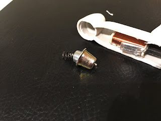
Note: The pin head is broken (that's the round shiny part on the bottom left of the above image).


It is basically a simple but smart lock. In normal condition, the spring pushes the ball holder (gray colored in the below demonstration) towards the casing (golden color). The balls therefore press against the pin and holds it tight. (There is actually a small notch on the pin to give more friction surface).


When the cashier places the tag against a strong magnet, the holder is pulled away from the casing:


Note that the spring is compressed, when the magnetic field is removed, the holder is pushed back to its original (locked) position.

Smart!


Tuesday, August 14, 2018

Garage Door Hack - Light Switch Remote for the Garage

Hello Everyone, it has been a long time (really long) since I last posted.

Anyways, here I am again, and I want to show you how I have made a remote for the garage in a funny way.

Okay, here is the background, my garage door remote does not work properly. Unfortunately, I tried to search for a manual to find out how to configure a new remote but no luck (It is a 433MHz system, and yes, I tried the "Register" button on all the different combinations).


Oh yea, this is a touch light switch, what is inside it?


Those two black rectangles are basically relays.... awesome!

This means I can simulate the manual push button using the relay contact!

So, I made a hole (using a drill) on the backside of the body:


I've also made a small modification to the circuit, the L (live) connection is disconnected and replaced with a wire which will go as a contact to the push button input:


Ok,time to go out:


Yeeeeees!

Program the remote control, test, done!

Close the box and remote away!


Saturday, December 3, 2011

Garage Door

Recently, we moved to another home, unfortunately (or fortunately) the garage door does not work, we open it manually currently, we requested the house owner to fix it but they said that they tried many times but failed, so what does this mean for an EE lover?

An awesomeness of course, a new toy to play with, a new game to reverse engineering :)

I tried the manual button, the motor does work but the door does not move, I tried assisting it by giving it a push but no hope, so apparently, the gears are broken/loose etc a mechanical problem in short.

not only that, but also, we do not have the remote controller, so apparently I'll have to hack it to put my own wireless connection, later..

now lets start playing:


The box:


Now I need to remove the bottom to reach the mechanical problem and fix it, I had to use a lot of force to open these two blots on bottom:


notice how the spanner got bended in the image below


What about this dried-sanded grease:


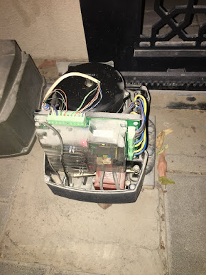
overview of the inside, 
top right is the motor with three wires (I don't have experience with motors, so your help is apperciated here, the motor has three wires two of them are connected the big cylinder you can see on the top left [I guess a cap??!] and there is a third wire)
What is this motor? which type? what are the three wires?
Is it a capacitor really? why it is there?

top left a capacitor (I guess)
below it is the transformer
and on bottom the PCB
Wireless chip on right side of PCB
Connection Header on top of PCB


The circuit 


started labeling some wires


I then used WD-40 and sprayed on the screws to remove the PCB (Along with the transformer which is soldered to the PCB)


Now I need to remove wires, so I took note of all connections and labeled wires


Before that, I decided to test it, found that the motor is actually rotating as well as the output shaft
so, I reconnected it up again, but again it does not work!!!

conclusion: the mechanical assembly is having a problem which I cannot fix

repairing attempt Failed!